39 electric motor diagram with labels
The picture shows a basic diagram of an electric motor. Which labels ... The picture shows a basic diagram of an electric motor. Which labels best complete the diagram? X: Brush Y: Armature Z: Commutator X: Commutator Y: Brush Z: Armature X: Armature Y: Commutator Z: Brush X: Armature Y: Brush Z: Commutator Expert-verified answer SerenaBochenek Motor Connection Diagrams (OLD LECTURE) - YouTube Please use the updated lecture at:
Electric Car Diagram - Car Construction Car Anatomy and Repair, Electric car, Engine, How a car Works, Construction. The active reference to source is obligatory if you use materials of a site Car Anatomy 888 shares

Electric motor diagram with labels
Draw a labelled diagram of an electric motor ... - Sarthaks eConnect Working of Electric Motor Current in the coil ABCD enters from the source battery through conducting brush X and flows back to the battery through brush Y. The current in arm AB of the coil flows from A to B. In arm CD it flows from C to D, that is, opposite to the direction of current through arm AB. Electrical Symbols For Schematic Diagrams | EdrawMax Step 1: Launch EdrawMax on your computer. An extensive collection of electrical diagram templates can be found in the Electrical Engineering category. Click the icon of Basic Electrical to open the library that includes all symbols for making electrical diagrams. Step 2.1: As you are into the workspace of EdrawMax, drag the symbol that you need ... Electric Motor Diagrams - Mr. Electrician's Home Page A Split Phase Capacitor Start Electric Motor may be defined as a form of split-phase motor having a capacitor connected in series with the auxiliary winding. The auxiliary circuit is opened by the centrifugal switch when the motor reaches 70 to 80 percent of synchronous speed. Also known as a capacitor-start, induction-run motor.
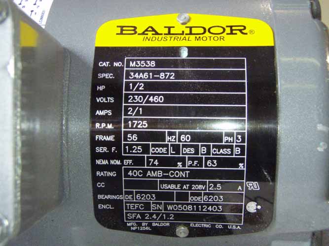
Electric motor diagram with labels. Single Phase Electric Motor Wiring Tutorial: Baldor, WEG, Leeson In this video, Jamie shows you how to read a wiring diagram and the basics of hooking up an electric air compressor motor. These tips can be used on most ele... Electrical Diagrams and Schematics - Inst Tools Types of Electrical Diagrams or Schematics. There are three ways to show electrical circuits. They are wiring, schematic, and pictorial diagrams. The two most commonly used are the wiring diagram and the schematic diagram. The uses of these two types of diagrams are compared in Table 1. The pictorial diagram is usually not found in engineering ... Electric Motor Nameplate Details Explained | Electric Motor ... The nameplate shown in Figure 1 indicates the electric motor is rated 1 HP. With a service factor of 1.15, the motor can be overloaded up to 1.15 horsepower. If the motor is operated in the service factor range continuously, it will cause a reduction in motor speed and efficiency, and an increase in the motor's operating temperature. Draw a labelled circuit diagram of a simple electric motor and explain ... A commercial electric motor is one which uses the following (i) An electromagnet in place of permanent magnet. (ii) Large number of turns conducting wire in current carrying coil. (iii) A soft iron core on which the coil is wound. The combination of soft iron core and coil is an armature. It enhances the power of motor.
Electric Motors Symbols - AC/DC, Single Phase / Three Phase Motors This is the symbol of a generic electrical motor that is used in electrical schematics. A motor converts electrical energy into mechanical energy. Dual Speed Motor This symbol represents a dual speed motor. Such type of motors has two separate windings for different speed ratios. Each winding provide different speed & torque at a single time. Explain the construction and working of the following. Draw a neat ... Draw a neat diagram and label it. Electric motor . Maharashtra State Board SSC (Marathi Semi-English) 10th Standard [इयत्ता १० वी] Question Papers 172. Textbook Solutions 10056. MCQ Online Tests 30. Important Solutions 1991. Question Bank Solutions 7383. Three Phase Motor Power & Control Wiring Diagrams Three Phase Motor Connection Star/Delta (Y-Δ) Reverse / Forward with - Timer Power & Control Diagram Starting & Stopping of 3-Phase Motor from more than One Place Power & Control diagrams Control 3-Phase Motor from more than Two buttons - Power & Control Diagrams ON / OFF Three-Phase Motor Connection Power & Control Schematic and Wiring Diagrams Draw a labeled diagram of an electric motor. Explain its principle and ... Working of electric motor: As shown in the diagram, when a current is passed through the coil PQRS the coil starts rotating anti clockwise because a downward force acts on length PQ and at the same time an upward force acts on RS. Therefore, the coil rotates in anti clockwise direction.
Parts of Motor, Working of Electric Motor & Uses - BYJUS Take two bar magnets and keep the poles facing each other with a small space in between. Now, take a small length of a conducting wire and make a loop. Keep this loop in between the space between the magnets such that it is still within the sphere of influence of the magnets. Now for the last bit. Connect the ends of the loop to battery terminals. PDF Understanding Electric Motor Nameplates Figure 2 is a view of the underside of an electric motor. The letters are NEMA standard letters and the actual dimensions for general purpose motors are shown in Table 1. The diameter of the bolt hole of the motor mounting bracket is letter H. The diameter is 1/32 of an in. larger than the bolt used for mounting. 7 Parts Of Simple Electric Motor And Function - AutoExpose The trunk, the magnet is placed on a pivot with the circuit in such a way that it can produce rotary motion when these two components interact. Electric Motor main Components 1. Stator Coil 2. Rotor Coil 3. Main Shaft 4. Brush 5. Bearing 6. Drive Pulley 7. Motor Housing Simple Motor Parts and their function 1. Stator / Armature Coil OMTEX CLASSES: Explain the construction and working of the following ... Question 2. Explain the construction and working of the following. Draw a neat diagram and label it. Electric motor. Answer: Electric motor - It converts electrical energy into mechanical energy.. Principle- When a current carrying conductor is placed normally in a magnetic field it experiences a force which rotates the conductor thus mechanical energy is generated.
Electrical Engineering World: The Electrical Circuit of Frost Refrigerator
What is an Electric Motor? with the Help of a Labelled Diagram ... An electric motor is a device that converts electrical energy into mechanical energy. Diagram: Electric motor Working of an electric motor: An electric motor works on the principle of magnetic effect of electric current.

Patent US4567416 - Device for controlling an electric motor - Google Patents
Electric Motor Symbols Electric Motor Symbols. Electric motors are electromechanical devices whose function is to transform electrical energy into mechanical energy through electromagnetic interactions. There are other engines ( generators) that produce electricity by exploiting the mechanical energy, such as alternators and dynamos.

NCERT Solutions, CBSE Sample Papers and Syllabus for Class 9 to 12 : Draw a labelled diagram of ...
Basic wiring for motor control - Technical data guide | EEP Wiring diagrams show the connections to the controller. Wiring diagrams, sometimes called " main " or " construction " diagrams, show the actual connection points for the wires to the components and terminals of the controller. Basic wiring for motor control - Technical data. They show the relative location of the components.

A Basic Guide to Understanding Pool Pump Motors
Motor Connection Diagrams - Electric Motor Warehouse Single Phase Terminal Markings Identified By Color: (NEMA Standards) 1-Blue 5-Black P1-No color assigned. 2-White 6-No color assigned P2-Brown. 3-Orange 7-No color assigned. 4-Yellow 8-Red. Three Phase Connections: Part Winding Start: 6 Leads NEMA Nomenclature: WYE or Delta Connected.

Patent US6876165 - Method for operating an electric motor, and an electric motor for carrying ...
labeled diagram simple electric motor Electromagnet diagram draw physics labelled electromagnets magnet iron magnetic construction igcse field switch relay describe neat solenoid poles core coil. Motor control circuit diagram / start stop 3 wire control. Generator dc construction parts field magnetic main system diagram pole armature machine circuit globe commutator electrical ...

Project: Electric Booger: Motor Basics
General Electric Motor Wiring Diagram - Database 3. Three-inch guideline. It's always better to have too much wire than not enough. There are wire extensions available if you finish up cutting them short, but the wiring will work better if it is intact. Since a rule of thumb, you'll want to have wiring that is very long to extend 3 inches outside of the electrical box.
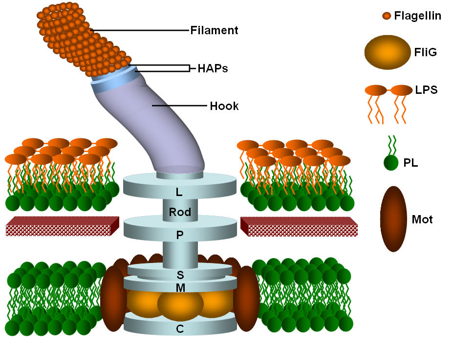
Bacterial flagella - nanotechnology
PDF Typical Electrical Drawing Symbols and Conventions. Basics 6 7.2 kV 3-Line Diagram : Basics 7 4.16 kV 3-Line Diagram : Basics 8 AOV Elementary & Block Diagram : Basics 9 4.16 kV Pump Schematic : Basics 10 480 V Pump Schematic : Basics 11 MOV Schematic (with Block included) Basics 12 12-/208 VAC Panel Diagram : Basics 13 Valve Limit Switch Legend : Basics 14 AOV Schematic (with Block included)

Electrical Engineering World: Basic Parts of a single phase pole-mounted distribution transformers
labeled diagram of electric motor labeled diagram of electric motor. How do electric motors work? - Explain that Stuff we have 9 Images about How do electric motors work? ... Century Electric Motor Wiring Diagram . phase baldor schematic volts waterway schematics forward peterbilt imageservice cleaver compressor chatroom emerson. Armstrong E8.2 - 3/4" - 1-1/2 ...

Patent US7073615 - System and method for operating an electric motor by limiting performance ...
PDF Electrical Symbols and Line Diagrams - University of Florida 4 Electric Motor Controls, G. Rockis, 2001 Manual Control Circuits Manual control circuit - any circuit that requires a person to initiate an action for the circuit to operate. A line diagram may be used to illustrate a manual control circuit of a pushbutton

Engineering Photos,Videos and Articels (Engineering Search Engine): Diagram of a wind turbine
Electric Motor - Principle, Working, Diagram - teachoo Electric Motor consists of Rectangular Coil of Wire ABCD A strong horseshoe magnet (or 2 different magnets ) - If we take 2 magnets, North Pole of first magnet faces South Pole of Other Magnet, as shown in figure... The coil is placed perpendicular to the magnet as shown in figure The ends of coil are connected to split rings - P & Q
Electric Motor Diagram High Resolution Stock Photography and Images - Alamy
Electric Motor Diagrams - Mr. Electrician's Home Page A Split Phase Capacitor Start Electric Motor may be defined as a form of split-phase motor having a capacitor connected in series with the auxiliary winding. The auxiliary circuit is opened by the centrifugal switch when the motor reaches 70 to 80 percent of synchronous speed. Also known as a capacitor-start, induction-run motor.
![[Get 31+] Draw The Schematic Diagram Of An Electric Motor And Label It Class 10](https://toppr-doubts-media.s3.amazonaws.com/images/9361982/9b8ef4cc-b55d-4f10-90af-7d760a903c84.jpg)
[Get 31+] Draw The Schematic Diagram Of An Electric Motor And Label It Class 10
Electrical Symbols For Schematic Diagrams | EdrawMax Step 1: Launch EdrawMax on your computer. An extensive collection of electrical diagram templates can be found in the Electrical Engineering category. Click the icon of Basic Electrical to open the library that includes all symbols for making electrical diagrams. Step 2.1: As you are into the workspace of EdrawMax, drag the symbol that you need ...

1000+ images about projects on Pinterest | Cars, Boats and Toys
Draw a labelled diagram of an electric motor ... - Sarthaks eConnect Working of Electric Motor Current in the coil ABCD enters from the source battery through conducting brush X and flows back to the battery through brush Y. The current in arm AB of the coil flows from A to B. In arm CD it flows from C to D, that is, opposite to the direction of current through arm AB.


andr01d.make: 2012-07
Electric Motor Data Sheet - Klistoff Equipment & Machinery, Inc. Tel: 503-982-0530
What is an electric motor? Explain its construction and working with the help of a labelled ...

DC motor parts - Electrical Engineering Books
Post a Comment for "39 electric motor diagram with labels"